
Electronic design
In this section the design of the chain of acquisition of the sensor signal is explained in details. A site helped a lot for this section (http://www.philohome.com/sensors/filoguide.htm) and was used to design the sensor acquisition.
The first step is to identify the physics that allows to sense a magnetic field. The phenomenon used to do so is called inductive guidance. The main idea is that around the alternative current flowing in a wire, a magnetic field is sensed by two coils. In fact when the magnetic flux through a coil is varying in time an electrostatic force in induced in the coil and implies there is a current and a voltage with the same frequency between the extrimities of the coil. This voltage is the signal that is treated by the electronic chain of acquisition.
The main idea here is to have two sensors (one right and on left) around the wire so when one of them is closer to the wire there is more voltage signal and thus the robot has to move in the opposite direction to come back to the original position (see Figure below).
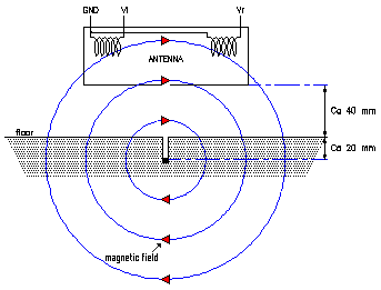
Figure: Magnetic field sensed by two coils sensors
Generator
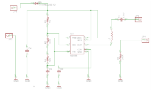
First, one has to generate a frequency of for example 50 kHz in the wire (frequency chosen high enough to avoid interfereces with the environment). This is done thanks to a timer NE555 converting a DC voltage into a square wave. Then a bandpass filter (LCR in series) is tuned on this frequency to get a sinusoïdal voltage of 50 kHz from the previous voltage. The inductance is chosen at 10 mH and so the capacity at 1 nF to get a signal frequency close to 50 kHz (50,3 kHz).
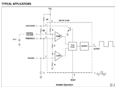
The final circuit is the following (for the astable operation, the duty cycle is accurately controlled with two external resistors and one capacitor, F= 1.49/[(Ra+2.Rb)C] see figure above) :
Its pcb design is detailed HERE
Sensors
To avoid to sense the noise during the acquisition, the coils are in parallel with a capacity and their values are chosen so that the resonnance frequency is exactly the one that is generated in the wire (50 kHz). The signal sensed is very low and thus has to be amplified during the acquisition. This is done thanks to an inverted amplificator which resistances are tuned to get a gain of 47 (see Philohome site). Moreover since only the maximum value of the signal (the amplitude) is important, one has first to use a rectifier to focus only on the positive part of the voltage. To do so the following rectifier amplificator is used because it is combining the two functions (Figure below).
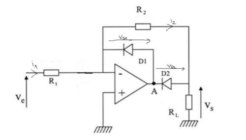
If Ve > 0 : Va is decreasing and thus D1 conducts, D2 limits the output Vs voltage to 0.6 V (threshhold voltage).
If Ve < 0 : Va is increasing and thus D2 conducts and D1 does not anymore, so the output voltage is equal to ( –R2/R1)* Ve (simple inverted amplificator).
After that there are two solutions :
-Peak picking with a capacity and a resistance was tested but there is a compromise between peak picking and following a change in the amplitude of the input voltage (if the uncharging time constant RC is large enough with respect to the frequency signal then peak picking works better but then if there is a change in the input amplitude, the delay is too long before the output changes because the capacity is decharging very slowly).
-FIltering the output with a low-pass filter to tke only the DC voltage and remove all the harmonics of the signal. This idea seems better and is chosen since it apparently worked for Philohome site’s author. R= 1k, C= 100 nF (low pass filter frequency at 1591,55 Hz).
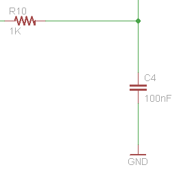
low_pass_filter
Finally the difference between the two sensors signals is computed thanks to a differential amplificator and the output signal is given as input to the arduino.
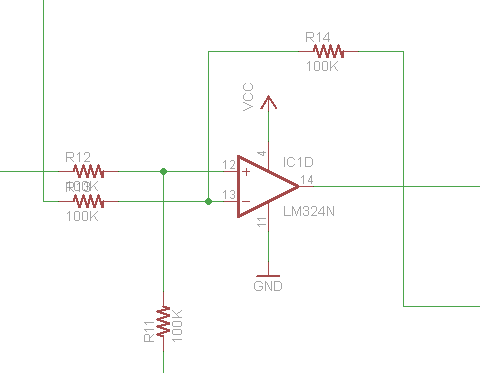
Differential amplificator
The final circuit is the following :
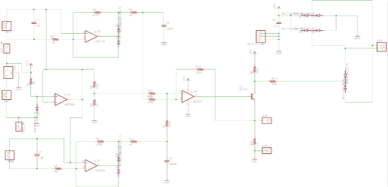
Sensor acquisition chain circuit
At the right of this schematic, the two resistors of 200 kohms are not resistors but open circuits. In fact we wanted at the output or :
-To put just a pull-up resistor (Vcc + resistor at the place of the first R 200k)
-To hold the circuit of Philohome by connecting a wire to short circuit the other 200 kOhm place (connecting the diode bridge)
The PCB of this part is explained and given HERE.
The purpose of IC1A amplificator is to avoid the offset of 0.6 V due to the diodes (the reference of the first 2 OP-amps are not at 0V but at 0.6 V, and the reference of the differential OP-amp is at 0.2V due to a resistor divisor, R9 (3.3k) and R8 (1k)) :
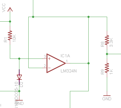
offset_on_the_reference
Finally, the code used to control the motors knowing the position of the robot with respect to the wire is shown and explained HERE.